
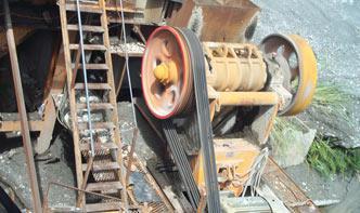
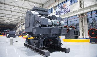
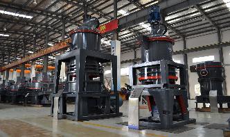
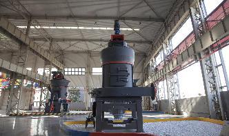
P Id Pipe Mill Equipment
PID
Piping and Instrumentation Diagrams or simply PIDs are the "schematics" used in the field of instrumentation and control (Automation) The PID is used to by field techs, engineers, and operators to better understand the process and how the instrumentation is inter connected. Process Analysis and Control PID Handout Page 2 . Temperature Process. Using pictorial diagrams may be informative ...
PRACTICAL PIPING COURSE
foundations, or any equipment excluded from Code definitions. Piping components are mechanical elements suitable for joining or assembly into pressuretight fluid containing piping systems. Components include pipe, tubing, fittings, flanges, gaskets, bolting, valves and devices such as expansion joints, flexible joints, pressure hoses, traps, strainers, inline portions of instruments and ...
PD720 PID's, Piping and Equipment Specifiions, Lists ...
PID's, Piping and Equipment Specifiions, Lists and Schedules Equipment Layout and Plot Plans Civil, structural, electrical, instrumentation, maintenance considerations Coordination of Front End tasks Piping and Equipment Arrangements, Describe the procedures involved in the layout and piping of a typical process unit containing pumps, exchangers, horizontal drums, storage ...
What is Piping and Instrumentation Diagram (PID) ?
A piping and instrumentation diagram/drawing (PID) is defined by the Institute of Instrumentation and Control as follows: A diagram which shows the interconnection of process equipment and the instrumentation used to control the process. In the process industry, a standard set of symbols is used to prepare drawings of processes.
Piping and Instrumentation Diagram (PID) Software
The PID diagram software comes with a rich set of highquality PID symbols for you to create different kinds of PID diagrams. Without a doubt, Visual Paradigm Online is the best PID software to create schematics for the process industry. With Visual Paradigm Online, you don't need to start each PID from scratch because a rich set of piping ...
UK
PM Rotating Process Equipment . Unit 1, Lodge Farm, Hook Road, North Warnborough, Hampshire RG29 1HA, United Kingdom
From BFD to PFD, PID, FID (Process)
· A PID drawing, instead, is a more detailed representation of the processes, including any minor or minor flow, any piping and instrumentation equipment, and the control loops that govern the system. PIDs diagrams are developed by intense cooperation of instrumentation, electrical, mechanical, safety engineers.

Piping Line Numbers on a PID
09/02/2008 · Piping Line Numbers on a PID Piping Line Numbers on a PID TTitsch (Electrical) (OP) 2 Jan 08 14:17. ... A process line that originates at a single nozzle on one piece of equipment (Vessel) and terminates at multiple nozzles on another piece of equipment (a multiple unit FinFan) will not normally change line number at the branch to the ...

PID, Isometric 2D piping plans
PID also comes with many features that will improve the accuracy of your project data. For example, you can create global lists for project instruments and equipment, as well as make global edits to valve and instrumentation data, which prevents costly mistakes. You'll absolutely love all the intelligent automation features that PID offers.
PIPING AND EQUIPMENT INSULATION
Piping and equipment shall be insulated according to the insulation class, operating temperature and insulation thickness stated in the PID and Data sheets. All insulation shall be covered with weather protection designed and installed to prevent ingress of water .
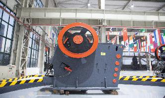
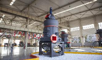
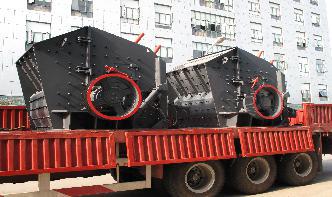
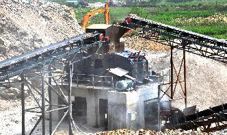
Welding Equipment and Consumables for Pipe Mill Industries ...
The Pittsburg, Calif.based pipe mill, a jointventure between Steel, SeAH and POSCO, uses an advanced automated twostep welding process that is capable of producing 300,000 net tons of line pipe per year. Outside diameters of produced spiral pipe range from 24 to 64 inches, using A252 through X80grade steel with wall thicknesses from ...

Basics of Piping and Instrumentation Diagrams (PIDs ...
PID stands for Piping and Instrumentation Diagram or Drawing. Alternatively, it could also be called Process and Instrumentation Diagram or simply PI diagram or drawing. PIDs are also known as Engineering Flow Diagrams or Mechanical Flow Diagrams .PIDs are often used in the process industry to show the process flow and other installed equipment and instruments. They show the ...
How to Read PID, PFD BFD used in Process Plant like Pro
Reading PID and PFD is nothing but understanding the symbols on the drawing. Before moving to the actual drawing, you will learn PID symbols that are used in these drawings. PID and PFD selected as an example cover all major components of process facilities such as refinery, power plant, petrochemical complex, and offshore oil platforms.
Preparation of AsBuilt Drawing, Piping Instrument (PID ...
· Once approved by the relevant department, the PID is then issued as "AsBuilt" PIDs to the client for final approval. The above image is not a PID Drawing but Piping .
PID Software
Sphera's Interactive PID software streamlines isolation planning with quick access to engineering documentation and interactive capabilities to markup piping and instrumentation diagrams. Now teams can view the realtime operational status of the asset, identify sources of operational risk as well as where to control and shutdown, and ensure regulatory requirements.
PID
Please provide credit to This work by is licensed under CC BYND stop animation stop. slide 2 of 2. PID means Piping And Instrumentation Diagram. PID is an abbreviation for Piping And Instrumentation Diagram.
(PPT) PIPING AND INSTRUMENTATION DIAGRAM PNID | .
PIPING AND INSTRUMENTATION DIAGRAM ( PNID) GP206 Leong Kok Seng Chapter 1 Symbols in Pipe Flow Diagram Introduction to PID What is PNID? >> Piping and Instrumentation Diagram • One of the basic plant drawings largely used in oil refining and other process industries. • The term "piping" means not only "pipe" but fitting, valves, flanges, and other items which form part of the ...
What does XV mean on a PID?
· A Definition of PID A PID shows all piping, including the "physical sequence of branches, reducers, valves, equipment, instrumentation and control interlocks." A PID is used to operate the process system, since it shows the piping of the process flow along with the installed equipment and instrumentation.
How to Read Oil and Gas PID Symbols | Kimray
How to Read Oil and Gas PID Symbols. In many industries, engineers will create a blueprint for equipment and control layout, called a Piping and Instrumentation Diagram, or PID. In this video, we'll walk through codes and symbols specifically for oil and gas production equipment so you can read and understand PIDs in the industry.
Piping and Instrumentation Symbols
Figure 8 shows symbols used to depict pipe fittings. Figure 8 : Piping Symbols. Instrumentation. One of the main purposes of a PID is to provide functional information about how instrumentation in a system or piece of equipment interfaces with the system or piece of equipment.
Process and Instrument Drawing (PID)
PID is sometimes referred to as a Piping and Instrumentation Drawing. These diagrams are also called flowsheets. PIDs are used by process technicians and instrument and electrical, mechanical, safety, and engineering personnel. In both diagrams arrows show the flow of material and symbols show tanks, valves, and other equipment. The symbols ...
Create a PID or PFD
A PFD is more conceptual than a PID, and usually includes more annotations that display data. Create a piping and instrumentation diagram. In Visio, open any of the following templates: Piping and Instrumentation Diagram. Process Flow Diagram. From any of the Equipment egories, drag equipment shapes onto the drawing page.
Intelligent PID Software
Visio ® PID Process Designer is an addon to Microsoft Visio ® software. It significantly improves the productivity of the user for creating Process Flow Diagrams (PFD's) and Piping Instrumentation Diagrams (PID's) in the Visio ® environment. It is cost effective, userfriendly and very easy to learn for any Microsoft Office user.
Plant Design | PID Design | Solid Edge
Solid Edge PID Design provides 2D flow diagram and symbol support to create PIDs, which are crucial for meeting company and international quality standards. It supports ANSI/ISA, DIN, and EN ISO standards and connects seamlessly to Solid Edge Piping Design where its definitions control automated 3D pipeline creation. Features that are defined in PID can be easily placed into a 3D model to ...