
A Label Diagram Of A Grinding Machine With Pulley
The Model South Bend 9inch
The Nell) 1937 Model South Bend 9inch <» W®rnlJ~)JJ®LP 00 p~ Lathe A BACKGEARED, SCREW CUTTING LATHE JANUARY 4. 1937 SOUTH BEND LATHE .
Operating Instructions and Parts Manual 8inch Bench Grinder
the machine and in this manual. Failure to comply with all of these warnings may cause serious injury. 3. Replace warning labels if they become obscured or removed. 4. Do not use this grinder for other than its intended use. If used for other purposes, JET disclaims any real or implied warranty and holds itself harmless from any injury that may
Labelled Diagram Of Grinding Machine
diagram of grinding machine with labelDiagram Of Grinding Machine With Labels diagram of grinding machine with label surface grinding machine parts labeled . surface grinding machine Machine tool Basic machine tools BritannicaGrinding machines remove small chips from metal parts that are brought into contact with a rotating abrasive wheel called a grinding wheel or an abrasive belt.
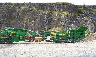
Belt Pulleys Turned Tractors into Portable Power Units ...
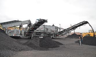
· Some other examples of the types of equipment powered through a tractor's flywheel or belt pulley, in addition to threshers and balers, are buzzsaws, hammer mills, burr mills, and pumps. Jobs included grinding feed for livestock, making shingles, cutting firewood, and much more.
Draw a Diagram to Show a Block and Tackle Pulley System ...
Draw a Diagram to Show a Block and Tackle Pulley System Having a Velocity Ratio of 3 Marking the Direction of Load(L), Effort(E) and Tension(T). CISCE ICSE Class 10. Question Papers 301. Textbook Solutions 25661. Important Solutions 2872. Question Bank Solutions 24328. Concept Notes ...
simple machines, simple machines Diagram | Quizlet
A simple machine that decreases the force needed to move an object, an inclined plane wrapped around a cylinder. (threads) force. push or pull. work. Accomplished when an object moves as a result of a force. load. object being lifted or moved. simple machines.
Atwood's Machine Lab Edited
each Free Body Diagram. We will use the standard practice of labeling masses from smallest to largest, therefore m2 > m1. For an Atwood's Machine there are only forces acting on the masses in the vertical direction so we will only need to write Force Summation Equations for the y‐direction.
Components of drilling machine and their functions ...
· In a drilling machine, singlephase ac motor is used, it can run at a rpm of 600 to 5000. More rpm is used for high drilling machine. The electric motor supply mechanical power from the pulley to the spindle and allows different speed. Pulley or gears. These components are used to transmit power and also for generating different speed.
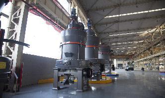
Types of Cylindrical grinding machine with Diagram Explained
Types of Cylindrical grinding machine with Diagram Explained. This machine is used to produce external cylindrical surface. The surfaces may be straight, tapered, steps or profiled. Broadly there are three different types of cylindrical grinding machine as follows: 1. Plain centre type cylindrical grinder. 2. Universal cylindrical surface grinder.
Diagrams Of A Grinding Machine
Diagrams Of A Grinding Machine. This machine is required for the precision grinding of various governing component seat, valve cone and mandrels etc to meet stringent specifiion of machine is as work piece material ferrous material like carbon steels, alloy steels, tool steels machine specifiion.
Levers, pulleys and gears – Key Stages 1 2
Levers, pulleys and gears appear the in the national curriculum in key stage 1 and key stage 2: Science in year 5. Forces: Recognise that some mechanisms, including levers, pulleys and gears, allow a smaller force to have a greater effect. Design technology in key stage 1
Operating Instructions and Parts Manual StepPulley ...
12. Make all machine adjustments or maintenance with the machine unplugged from the power source. 13. Remove adjusting keys and wrenches. Form a habit of checking to see that keys and adjusting wrenches are removed from the machine before turning it on. 14. Keep safety guards in place at all times when the machine is in use. If removed for
Pulley systems
· Pulleys use mechanical advantage, similar to levers, to lift up loads. Pulleys are wheel shaped with a groove that allows a cord to sit inside the groove. They .
![Drilling Machine [Parts, Types, Tools, Operations] with PDF](/viqdyfp/563.jpg)
![Drilling Machine [Parts, Types, Tools, Operations] with PDF](/viqdyfp/252.jpg)
Drilling Machine [Parts, Types, Tools, Operations] with PDF
· The drilling machine is defined as a machine which is used to make a circular hole, a tool used to drill the holes of different size and other related operations using a drill bit.. The drilling machine is one of the most important machines in a workshop. As regards its importance it is second only to the lathe were drilled by the Egyptians in 1200 about 3000 years ago by ...
Parts Of Grinding Machine With Labels
diagram of grinding machine with label draw a well ... vintage coffee grinders notice air pressure 30 psi for cleaning parts and equipment label safety first ... Detail About. Grinding Machine Labeled. labeled parts of grinding machine Mining Crusher Manufacturers .
Lathe Machine – All Parts and Functions with Diagrams and ...
· Lathe Machine. The removal of material from metal is called Machining, and the process usually happens in a machine shop that has special equipment. Parts of lathe machine Headstock: The headstock is fixed on the machine and it consists of many .
labelled diagram of a grinding machine
Grinding Machine Labelled gezinsbondmeldertbea well labelled grinding machine shibang china. labelled diagram of grinding machine Mine Rice milling machine complete information This model is a multi functional Rice milling machine which mainly consist of a milling machine a grinder Label G is on Grinding materials entrance the machine movement parts to ensure all are well fixed and are ...
diagram of a grinding machine
A grinding machine, often shortened to grinder, is one of power tools or machine tools used for grinding, it is a type of machining using an abrasive wheel as the cutting tool. Each grain of abrasive on the wheel 39;s surface cuts a small chip from the workpiece via shear deformation.
Science Ch. 3 Physics Flashcards | Quizlet
Science Ch. 3 Physics. What are the two simple machines that take advantage of turning. Nice work! You just studied 35 terms! Now up your study game with Learn mode.
What Are the Different Pulley Parts? (with pictures)
Pulleys vary in how the different pulley parts are organized. The fixed pulley is one where the grooved wheel has a fixed axle, and the whole machine is attached to a surface. This type of pulley provides no real mechanical advantage as it still requires a person to apply the same amount of force; it only changes the direction of the force applied.
How to Calculate First, Second and Third Pulley Systems ...
· The article discusses three popular systems of pulleys and discretely explains the involved operational mechanisms. The systems basically include different groups of pulley/string mechanisms, each involving a specific pattern of movement for lifting the attached weight in response to the applied effort. All the systems basically are designed with one common focus that is to make the involved ...