
Sinter Plant Block Diagram
Sintering | Eurotherm by Schneider Electric
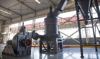
Figure 1 shows a simplified diagram of a sinter plant. Materials enter the sinter plant from storage bins. They are mixed in the correct proportions using weigh hoppers, one per storage bin, except for the return fines for which an impact meter is used instead. Weighing is continuous, as .
Sinter Plant Windbox Gas Recirculation System ...
However, each plant can be divided into three distinct phases of operation, namely, (1) raw materials processing, (2) sinter production and (3) product processing. A schematic flow diagram of a typical modern sinter plant is shown in Figure 2. The inbound raw ore is first screened to the maximum size desired for the blast furnace coarse ore.
iron ore pellet plant process flow diagram tanzania
Sinter plant flow chart process flow diagram of iron ore processing plant pellet process uses and exposures pellet production in the five eu plants process flow diagram of iron ore processing plant mentioned above was 151 mt in 1996 2 this written process along with the flow diagram is taken as a base reference the mixture of iron bearing.
Final Report : Test Report of Sinter Plant Emissions at ...
REPORT NO. Y847918 PAGE FIGURE IIIl III2 IV1 IV 2 IV 3 IV 4 IV 5 IV 6 IV 7 IV 8 IV 9 Vl V2 V3 V4 V5 V6 V7 V8 V9 V10 Vll V12 Vl 3 V14 Vl 5 Vl 6 Vl 7 LIST OF FIGURES Simplified Schematic of Sintering Process Sinter Plant Flow Diagram Discharge Baghouse Outlet Test Loions No. 2 Windbox ESP Inlet Test Loion No. 2 Windbox ESP Outlet Test Loion Baghouse ...
Sinter Plant Process
Sinter plant process diagram a sinter plant supplies the blast furnaces with sinter, a combination of iron ore, fluxes and cokehese finegrained materials are mixed in the correct proportions and heated in vacuumhe high temperatures cause the iron ore. Chat Online; 030301 Sinter Plants.
sinter plant diagram
an Iron Ore Sintering Plant Based on the mathematic model and using the Simulink program from Matlab environment, were executed the diagrams that achieve the simulation of the dosing subprocess of the sintering ores, as well as the simulation of the iron ores' sintering subprocess [4,11].The subsystem from fig. 2 makes the
Steel Times International November December 2016 by Quartz ...
Nov 29, 2016 · Productivity and sinter quality are best when sinter lines are operated at peak permeability (Pmax). System design The sintering facilities at the Bokaro sinter plant .
sinter plant process flow diagram
Sinter plant process flow diagram in jsw Products. As a leading global manufacturer of crushing, grinding and mining equipments, we offer advanced, reasonable solutions for any sizereduction requirements including, Sinter plant process flow diagram .

heat mass balance diagram power plant design calculation
Heat balance diagram SlideShare. · Heat balance diagram. 1. Index PLANT BLOCK DIAGRAM PLANT RANKINE CYCLE HIP HEAT MASS BALANCE LP HEAT MASS BALANCE HEAT RATE Important Formulae. 2. Plant BLOCK DIAGRAM HRH P= LPT Inlet 41, T = 566, G= P=,, G= H=, Main H= Steam P = HPT LPT LPT IPT 242, T = Gr ...

Sinter plant process flow diagram in jsw
Sinter plant process flow diagram in jsw Products. As a leading global manufacturer of crushing, grinding and mining equipments, we offer advanced, reasonable solutions for any sizereduction requirements including, Sinter plant process flow diagram .
How lead is made
It is captured at a separate acid plant and converted to sulfuric acid, which has many uses. After the ore has been roasted in this way, it fuses into a brittle material called sinter. The sinter is mostly lead oxide, but it can also contain oxides of zinc, iron, and silicon, some lime, and sulfur.
Pollution Effects of Abnormal Operations in Iron and Steel ...
A cooler emission of kg/Mg of sinter has been measured, however, and at least one plant has installed a 23 fabric filter on a cooler discharge. Process Modifiion A recent variation in the design and operation of sinter plants is to recycle about 40 percent of the gases from the windboxes at the entry of the sinter machine to the ...
Sinter Plant Layout Diagram
Sinter Plant Layout Diagram. PDCF layout and deployment process flow of crusher equipment process transfer point in crusher plant understanding sinter and sinter plant operation sintering is caused by heat generated by combustion, and fine mineral particles are .
Plant Monitoring System – IJERT
Jun 09, 2021 · CIRCUIT DIAGRAM. Fig 6. Circuit Diagram. Fig 7. System Setup. WORKING. Fig . Shows the block diagram of Plant Watering System with I0T. User monitors and control system in order to improve the efficiency with help of sensor parameters like temperature, humidity, soil moisture. Fig 8. Working Project. Fig 9. Working Hardware. Fig 10. Working Display
flow process sinter plant
Flow Diagram Of Sinter Plant System Fertilizer Gulin Least News Optimizing manganese ore sinter plants: process parameters and design impliions » The More » dexpan, Sinter Plant Process Flow Diagram flow diagram of sinter plant system for production . Traveling Grate Sinter Plant Outotec.
Schematic Diagram Of Hydro Power Plant
Hydro Power Plant Block Diagram Explain The Working And . Hydro Power Plant Construction And Arrangement Diagram . Hydro Power Plant Structure Design Pdf File Cadbull . Diagram Inside Dam Wiring Diagram 500 . Hydropower Plant Sea Trasformatori . Schematic Diagram Of Sundarizal Mini Hydro Power Plant .
Apparatus for temperature controlled laser sintering ...
FIG. 1 is a schematic block diagram of a prior art sintering system. FIG. 2 is a schematic block diagram of a sintering system with thermal feedback control of laser power in accordance with the present invention. FIG. 3 is a schematic block diagram of a control system for thermal control of laser power in accordance with the present invention.

Experimental equipment at Fukuyama No. 4 Sinter Plant ...
Download scientific diagram | Experimental equipment at Fukuyama No. 4 Sinter Plant. from publiion: Effect of Highphosphorous Iron Ore Distribution in Quasiparticle on Melt Fluidity and ...
An adaptive intelligent system to minimize energy use for ...
Mar 21, 2019 · The modules consist of the engine, machine, brake and load which interact with the vehicle driveshaft to produce the driveshaft torque and speed. Other components consist of the battery and converter models. The overall block diagram appears in Fig. 2, where T e, T m, T b and T L are engine, machine, brake and load torques, respectively.
process flow diagram of sinter plant
Sinter plant process flow diagram sinter plant process flow atapril 25, 2013 1180 ratings sintering 1 shows a simplified diagram of a sinter enter the weighing is continuous, as is the whole sintering process. flow diagram of sinter plant system fertilizer
integrated steel plant process flow diagram
Schematic diagram showing the material flow in a sinter plant (Anon 1, 2014). The sintering process begins with the preparation of a sinter mixture consisting of iron ore fines, fluxes, solid fuel (called bonding agents in Japan) such as coke breeze, and return fines from the sinter plant . Read More
Process Control System – IspatGuru
Dec 28, 2013 · Fig 1 Block diagram showing various control elements. There are two main reasons for control. The first reason for control is to maintain the measured variable at its desired value when disturbances occur. The second reason for control is to respond to changes in the desired values of the process parameters.