
Flow Diagram For Concrete
UML: Fundamental UML Diagrams for HighLevel Conceptual ...
Fundamental UML Diagrams for HighLevel Conceptual Modeling The Use Case Diagram, ... possible flow of activity (workflow) ... • Concept gives rise to ABSTRACT and CONCRETE classes • Abstract classes cannot have any objects • Concrete classes can have objects

Process Flow vs. Data Flow Diagrams for Threat Modeling
· Process Flow Diagrams Process Flow Diagram of an online banking appliion. By sharp contrast, process flow diagrams provide a visual decomposition specifically designed for illustrating how attackers think. Attackers do not analyze data flows. Rather, they map out how they can move through the various appliion usecases.
Regulation 31 Approval Routes Flow Diagram
The flow diagram on the right shows what approvals would be required for an item depending upon whether it is large or small surface area. A calculation can be performed to work out a number (known as a 'C score'). This will determine if an item will be classified as a large or small surface area one for its intended use. Once you know this


Flow Net – Properties and Appliions
Properties of Flow Net. Properties of flow net are as follows: The angle of intersection between each flow line and an equipotential line must be 90 o which means they should be orthogonal to each other. Two flow lines or two equipotential lines can never cross each other. Equal quantity of seepage occurs in each flow channel.

Functional Flow Block Diagrams – System Engineering
· Functional Flow Block Diagrams. A Functional Flow Block Diagram (FFBD) is a simple way to show the sequential relationships between a set of Functions . The original concept can be extended to make it more useful to later stages of Developmental Engineering, having little arcane symbology and requiring no proprietary software tools 1 .
CAUSEANDEFFECT DIAGRAM
Diagram construction and analysis on the next few pages is based on a chart in The Memory Jogger [Ref. 1, p. 28]. This diagram has been broken down into its component parts and expanded to illustrate the construction steps. Using this example, we will diagram .

GROUNDWATER FLOW NETS Graphical Solutions to the Flow ...
equipotential lines are perpendicular to noflow boundaries form squares by intersecting stream and equipotential lines A sand filter has its base at 0 meters and is 10 meters high. It is the same from top to bottom. A plan view, toscale diagram of it is shown below. There is .

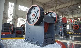
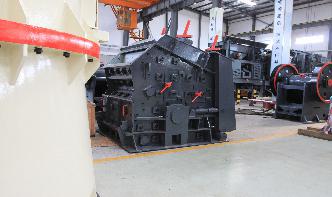
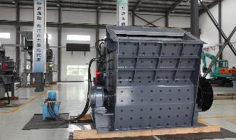
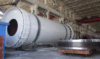
portable concrete plant flow diagram | Ore plant ...
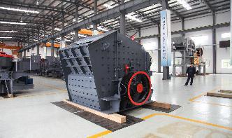
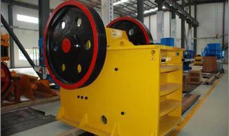
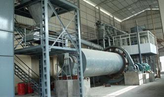
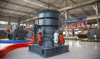
· Concrete Production Line Flow Chart . business plan for a grinding mill. flow diagram for portable crushing | Gulin Solutions . Portable crusher flow diagram Oman appliciation, layout siting picture. . coal crushing plant; portable concrete plants; concrete crushing plant . Block Diagram Chart Of Cement Plant – Ore Beneficiation Plant.
5 Tests to Measure the Workability of Concrete!
· Flow Test. VeeBee Consistometer Test. Kelly Ball Test. 01. Slump Test. The concrete slump test or slump cone test is the most common test for workability of freshly mixed concrete which can be performed either at the working site/field or in the laboratory. To maintain the workability and quality of fresh concrete, it is necessary to check ...
Integrating UML Diagrams for Production Control Systems
This paper proposes to use SDL block diagrams, UML class diagrams, and UML behavior diagrams like collaboration ... build up the concrete states of a system. ... UML activity diagrams as highlevel control flow notation for graph rewrite rules, cf. [JZ98, FNTZ98].
Online Diagram Flowchart Templates | Moqups
Online templates designed to support your projects. We offer a full range of templates and this dedied collection of flowchart stencils makes it easy to create any type of diagram. Smart Connectors attach quickly – and stay connected as you update your content. Diagram Extenders make expanding a flow as simple as a keystroke.

Introduction
expected flow at any point, provided that where a minimum size of pipe is stated in a paragraph, Table or Diagram that size of pipe shall be expected flow depends on the type, number and grouping of appliances and the flow rates given in Table 2 shall be assumed. Water seals (traps) All points of discharge into a system shall

SECTION 1 INTRODUCTION TO POST TENSIONED CONCRETE
NOTE: MOMENT DIAGRAM CONVENTION • In PT design, it is preferable to draw moment diagrams to the tensile face of the concrete section. The tensile face indies what portion of the beam requires reinforcing for strength. • When moment is drawn on the tension side, the diagram matches the general drape of the tendons. The tendons

Regular Paper UML 2 Activity Model Support for Systems ...
tional flow diagram. 2. Data/object/item flow: These are how a flow diagram routes data, objects, and other items, such as energy and matter, between functions. 3. Control: These are how a flow diagram starts and stops execution of functions. For clarity, this paper introduces two terms for concepts that are implicit in EFFBD and UMLSE but not

Free Civil Engineering Files for Downloading ...
Meyerhof bearing capacity calculator. meyerhof method, shallow foundation bearing capacity, mayerhof method, download civil engineering sheets. View all files of Foundation Analysis and Design. Load Calculation. Beam Analysis EXCEL Spreadsheet. shear force diagram, bending moment diagram.

How to Create an Order Process Flowchart
· And order process flowchart is a diagram to describe the systematic flow of the whole process from the suppliers to customers and show relationship between the major parts of the process. Functions of Flowchart Flowchart is a wonderful tool used to describe complied ideas or process in a visual and graphical manner.