
Circuit Diagram Of Car Crusher And Their Explanation

CHAPTER VIII FINITE STATE MACHINES (FSM)
SEQ. CIRCUITS INTRODUCTION FINITE STATE MACHINES •STATE TABLESTRANSLATE DIAGRAMPATTERN DETECT EX.TRANSLATE TO DIAGRAM • With the descriptions of a FSM as a state diagram and a state table, the next question is how to develop a sequential circuit, or logic diagram from the FSM. • Effectively, we wish to form a circuit as follows. Inputs ...
A1 HOW TO READ THE WIRING DIAGRAMS
A4 HOW TO READ THE WIRING DIAGRAMS How to Read Circuit Diagrams HOW TO READ CIRCUIT DIAGRAMS The circuit of each system from fuse (or fusible link) to earth is shown. The power supply is shown at the top and the earth at the bottom to facilitate understanding of the current flow.

How Circuits Work | HowStuffWorks
The diagram above shows a simple circuit of a flashlight with a battery at one end and a flashlight bulb at the other end. When the switch is off, a complete circuit will not exist, and there will be no current. When the switch is on, there will be a complete circuit and a .
Circuit Diagram: How To Read And Understand Any Schematic
· A circuit diagram, or a schematic diagram, is a technical drawing of how to connect electronic components to get a certain function. Each electronic component has a symbol. After seeing a few circuit diagrams, you'll quickly learn how to distinguish the different symbols. A .
WaterLevel Controller | Full Circuit Diagram with Explanation
· Waterlevel controller circuit WaterLevel Controller Circuit. When there is enough water in the underground tank, probes C and S are connected through water. As a result, transistor T1 gets forward biased and starts conducting. This, in turn, switches transistor T2 on.
Typical Wiring Diagrams for Push Button Control ...
Typical Wiring Diagrams For Push Button Control Stations 3 Genera/ Information Each circuit is illustrated with a control circuit (continued) schematic or line diagram and a control station wiring diagram. l The schematic or line diagram includes all the components of .
Working Of Hybrid Cars
When a car uses two different ideas to move, it is called a hybrid car. Usually our cars run on petrol, diesel or gas. But their inefficiency, as explained earlier, led to the invention of electric cars. But, since electric cars also had disadvantages of frequent battery charging and inefficient long drives, there evolved a combination of both.
How car electrical systems work | How a Car Works
Most car handbooks and service manuals include a wiring diagram which can be difficult to follow. The colourcoding, however, is a useful guide to tracing wiring. Where wires run sidebyside they are bound together in a bundle, in a plastic or fabric sheath, to keep them tidy and less difficult to fit .
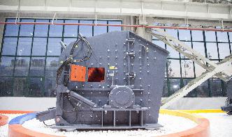
Circuit Diagram Of Crushing Control Crusher
Circuit Diagram Of Crushing Control Pricemanufacturers ... Circuit Diagramof Car Crusher And Their Explanation. ... crushing machine including a vehicle body that is equipped no way to limit the present invention but to facilitate an explanation and understanding thereof 4 is a circuit diagram illustrating another crusher drive control ...
The Schematic Diagram: A Basic Element of Circuit Design ...
2 days ago · The Schematic Diagram: A Basic Element of Circuit Design. by Anne Mahaffey Download PDF. There seems to be a limitless amount of information that can be learned in the field of electrical engineering. One of the most essential skills for an electrical engineer is the ability to read and create schematics. Before you start learning Ohm's law ...
Traffic Light Control System
· In the above circuit diagram of traffic light controller,a sevensegment display is used as a counter display, and three LEDs are used for the purpose of traffic light control. An 8051 Microcontroller is the brain of this whole project and is used to initiate the traffic signal at the intersections on road.
Circuit Diagram And Its Components
A circuit diagram is a simplified representation of the components of an electrical circuit using either the images of the distinct parts or standard symbols. It shows the relative positions of all the elements and their connections to one another. It is often used to provide a visual representation of the circuit .
Basics of Automotive Electrical Circuits
Basics of Automotive Electrical Circuits. Cars and light trucks have extensive electrical systems with lots of wiring and hundreds of circuits. An electrical circuit is basically a route or path through which electrons flow. An electrical circuit must form a complete loop so the current will continue to flow.
200+ Electronic Circuits
Electronic Circuits. Electronic is fun to learn, especially if you can learn it by building your own circuits. To help you with that, Circuit Digest provides you with a list of popular Electronic circuits and Electronic projects with well illustrated circuit diagram and detailed explanation .
Forward/Reverse Control Circuits – Basic Motor Control
Forward/Reverse control circuit. When designing the control schematic for forward / reverse circuits, we start with the standard. threewire circuit., add a second normally open pushbutton, and add a holding contact branch for the second coil. A single stop button is sufficient to disable the motor in both directions.

Crushing Plant Design and Layout Considerations
• Electronic control of crusher discharge opening and feed rate. With adjustment of a crusher's discharge opening, as the production continues through an online coarse size analysis of the crushed product (digital image analyses). Dance, A. 2001) • More attention is being paid to the impact on crushing circuit design caused by variations

100+ Power supply circuit diagram with PCB
· UPS Circuits Diagram; Switching Mode Power Supply circuits. These are DC switching power supplies. To be ideas on building the projects or tools. Because they have a small size and cheaper than the linear power supply. My site begins to have many circuits.
Fundamentals of Electronic Circuit Design
circuit by providing any amount of voltage across its terminals necessary to do so. Voltage and current sources can be independent or dependent. Their respective circuit symbols are shown in Figure Independent sources are usually shown as a circle while dependent sources are usually shown as a diamondshape. Independent
Circuit Drawings and Wiring Diagrams
Electrician Circuit Drawings and Wiring Diagrams Youth Explore Trades Skills 3 Pictorial diagram: a diagram that represents the elements of a system using abstract, graphic drawings or realistic pictures. Schematic diagram: a diagram that uses lines to represent the .

GSM GPS Based Vehicle Tracking System | Circuit with ...
· This GPS based vehicle tracking system implements RS232 protocol for serial communiion between the microcontroller, GPS and GSM modem. A serial driver IC MAX232 (IC3) is used for converting RS232 voltage levels into TTL voltage levels. The user's mobile number should be included in the source code written for the microcontroller.